A very double-edged sword, this one. The AE Scan Tool is very powerful, but can also be the most obnoxious tool you have ever used. This is a tool that remains in my toolbox for the fact that when I need it, it’s absolutely wonderful, but if I don’t absolutely have to have it, it stays tucked away in the darkest corner of my box.
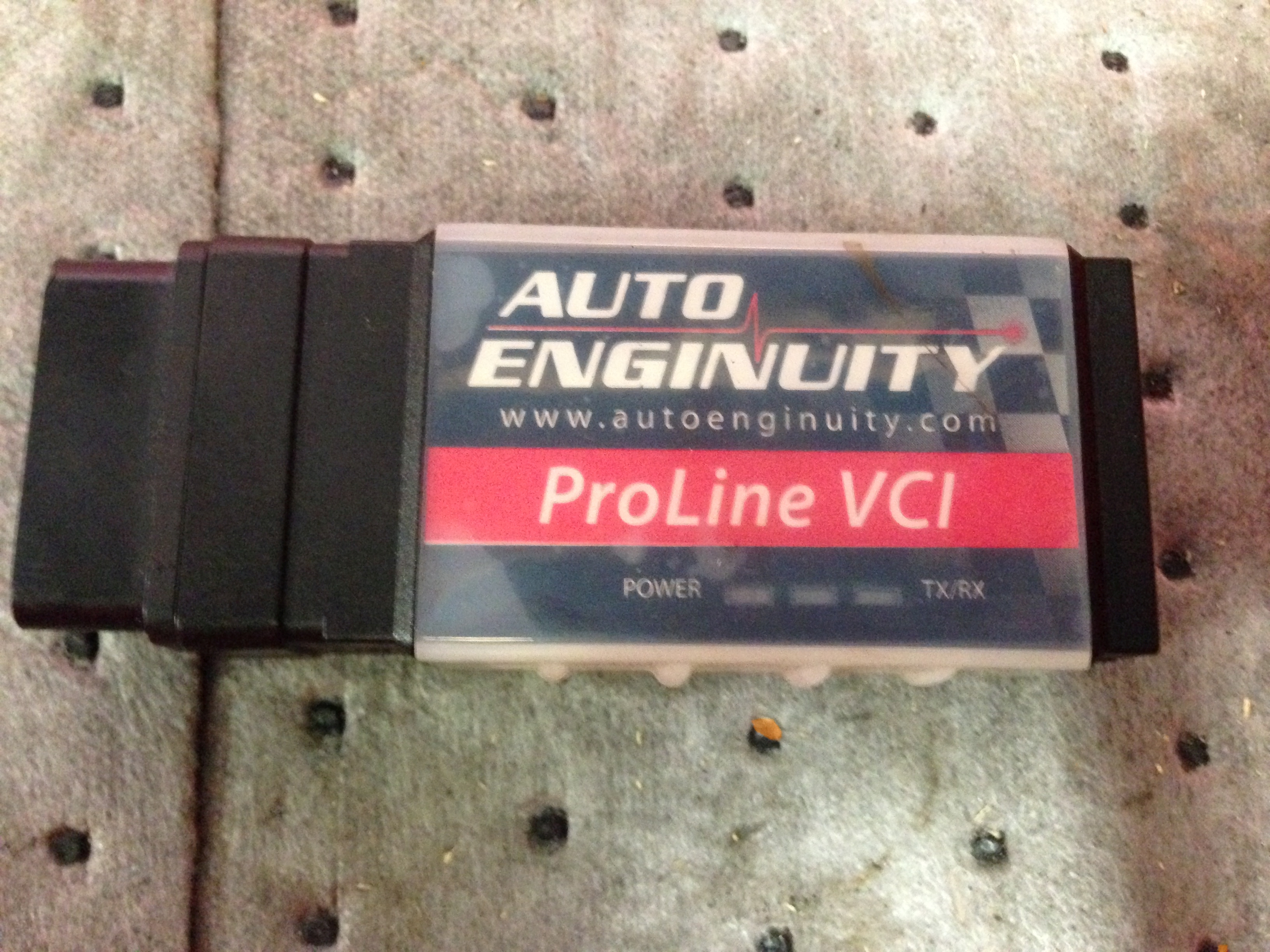
The AE Scan Tool consists of the ProLine VCI pictured above, software CD, and a USB cable. If you get the enhanced options then you can also get a BMW 20-pin connector, Mercedes-Benz 38-pin connector, and Nissan DDLI connector. There is also a Porsche cup car cable that I am unfamiliar with.
You will require a Windows PC to use with this tool. After installing the software and getting everything activated, you just hook the AE Scan Tool to the computer, to the car, start the software, and hope that everything is working correctly to this point and continues to work correctly going forward. The issues most commonly dealt with are the software saying that it cannot connect to the VCI or that it is unable to detect the vehicle’s protocol. This is usually corrected by redoing your connections and restarting the software and trying to do everything in a very picky order.
After hookup comes vehicle identification, by manual or automatic means. The software will try to Auto ID any vehicle that you connect to, which I like having the option of from the beginning. This Auto ID strategy is the same as the OTC Genisys Touch, unlike the SnapOn Solus Ultra where you usually have to enter a make and year for the tool to decide whether or not it will grace you with an Auto ID function. Once the vehicle’s information is supplied and a controller selected to connect to, then the tool goes through a process of detecting supported PID’s, which can be time consuming on some cars. Once this process has finished you will have an option to scan the currently selected module for codes, all vehicle modules, or not scan any modules at this time. Also, during module selection, just because the tool has a controller listed for a vehicle, that does not mean that it is capable of communicating with that module, contrary to AE tech support. Case in point on this note would be the door control modules of a 2003 Mercedes-Benz CL500 as of software version 12.0.
There is a bit of a learning curve to the AE software, as it does pack quite a bit of functionality into its interface. There are nine main areas to the software once you have connected to the vehicle. The Diagnostic Trouble Codes tab offers reading and clearing functionality to the connected module and all other modules supported for the vehicle, this tab, in my experience, will try to refresh itself from time to time with a popup asking to pull codes from the selected module, all modules, or none; this is the same behavior that happens upon initially connecting to the vehicle, and can be somewhat annoying in my opinion.
The next four tabs are all for live data display and graphing. The Live Data Meter gives nine large retro-LCD style displays, and each display has a units symbol below it to let you know what unit the PID is measured in and a drop-down box below that to select the PID that you want displayed. The next two tabs are for graphing, one for two graphs, and one for four. The graphs on the 2x tab run horizontal across the screen, and each graph has a drop down box for two PID’s. This gives you the option of displaying up to four color-coded PID’s across two separate graphs. The 4x tab puts all four PID’s into one vertically larger graphing plane. The last of the data graphing tabs is the Live Data Grid. This tab gives you a vertical listing of PID’s with check boxes next to each and a select all check box as well. The selected PID’s are displayed in rows containing the PID name, current value, unit the value is measured in, minimum and maximum allowable values, and then a horizontal bar graph that updates with the current PID value. The live data grid is my most used method to view live data, as it incorporates both the numeric value and an easy-to-see graph to spot if the value goes exceptionally low or high. This area of the software is also responsible for one my biggest complaints; the PID selection lists are in no logical order. The listing is not alphabetical, and can not be made so, nor does it follow any other discernible pattern of organization. Since the software will sometimes show numerous pages of PID’s, you may find yourself weeding through the listings trying to find a specific one, and most likely looking over it once or twice on the way.
The next section of the software is the O2 Sensors tab which gives you a graph for two oxygen sensor related PID’s selected by drop-down boxes. Below the graph is an area for data the technician may find useful such as threshold voltages and switch times for the oxygen sensors. There is also a sample oxygen sensor waveform that defines the areas of the waveform as listed in the useful data section.
The Test OnBoard Systems tab is next up. This is the area where you can go into items such as Volkswagen/Audi basic settings, Ford KOER/KOEO, or an evap service bay test. This area of the software is very unforgiving in guidance, and basically advises that you should know what you are doing before messing with anything here. This is true, as the only help really offered by this section or AE tech support is usually to “reference the vehicle’s service information.” There are two warnings at the top of this section advising these cautions.
The last tab in this grouping is for OnBoard Test Results. This section will give you Mode $06 data as well as your readiness for the IM monitors. The readiness section is nice due to the color coding. It is very easy to see if something hasn’t passed just by the looking for the test that isn’t green.
The final main section of the software is the Actuations tab all by its lonesome at the bottom of the page. Hovering the mouse over this tab will bring up an area where the technician can access all supported bi-directional controls for the vehicle. There is a check-box to click to take the test from inactive to active, the next click takes it to a grayed out state that I’m not sure means if it’s on or off, and the third click on the check box will bring it back to its original unselected state. The parameters that you can supply to the actuation are in a drop-down box, and may include values such as “On”, “Off”, “High”, “Low”, or some percentage value. This area will normally auto-hide itself once you move the mouse out of its boundaries, but can be made to stay by pressing the auto-hide button.
There are other parts to the software that are less technical and may be seldom used. Among other things, there is a unit conversion calculator, and a DTC definition tool that can come in quite handy. Everything else is fairly basic such as software settings or help manuals.
The last part of the software that I feel merits review is the technical support. The staff at AE are very courteous and always attempt to help me with any questions that I have. That said, I find myself wondering if they are overly-optimistic or even misled at times. This is often displayed in the attitude that if the software has an option then the option is obviously supported, or that perhaps the vehicle is what’s at fault for not supporting the action. The other instance that sticks out in my mind is being told for a problem that I had for awhile with the tool losing connection to the car after cranking that “basically every” scan tool will lose communication with the vehicle when started. Not just by losing live-data communication but by completely having to reconnect to the vehicle, which I haven’t found to be true on any of my other scan tools.
Overall the Auto Enginuity Scan Tool is very powerful, but it also has some quirks that make it quite cumbersome to use on a regular basis. It’s a very love-hate relationship that I feel most will form with this tool.